Examine This Report on Wedge Barriers

In the following conversation, recommendation is made to a surface of a foundation to which the wedge-style obstacle is installed. For instance, in the detailed embodiments, the top side of the support is considerably flush with the surface area of the foundation. In such embodiments, the wedge-style obstacle might be placed straight to the surface area of the foundation. However, in other personifications, the upper side of the anchor may be slightly increased above the surface of the structure or a little recessed listed below the surface area of the structure. 1 is a front viewpoint sight of an embodiment of a surface-mounted wedge-style obstacle 10. As shown, the barrier 10 is installed to a surface 12 of a structure 14(e. g., a shallow structure ). The structure
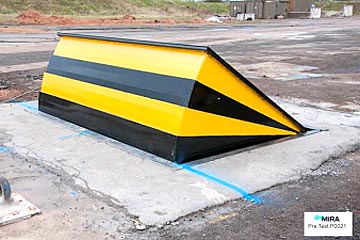
14 and the surface 12 surface area which the barrier 10 obstacle secured may safeguarded might from concrete. 2, the obstacle 10 is installed to or consists of an anchor or subframe (e. g., support 30 received FIG. 2 )protected under the surface 12. For instance, the bather 10 might be bolted to the anchor or safeguarded to the support by various other mechanical fasteners. In the detailed embodiment, the barrier 10 includes a wedge plate 16, which consists of a portion that is substantially parallel with the surface area 12 when the barrier 10 is in the pulled back placement. To put it simply, automobiles or individuals might pass over the obstacle 10 when the barrier 10 remains in the retracted placement and experience minor elevation family member to the surface area 12 while on the obstacle 10. As talked about carefully listed below, when the obstacle 10 is in the deployed setting, the wedge plate 16 is held and sustained in an elevated position by a training device of the barrier 10. Furthermore, the components 18 might be bolted or otherwise mechanically combined to one an additional. In this fashion, fixing or replacement of several elements 18 may be streamlined and structured. That is, repair service or replacement of solitary components
18 may be done more promptly, quickly, and price successfully. FIG. In particular embodiments, the anchor 30 may be a steel framework including plates, beams(e. g., I-beams ), and/or various other frameworks that are safeguarded within the foundation 14, which may be concrete. At the surface area 12, a top side 28 of the support 30 may be at least partly exposed
, consequently enabling the attachment of the barrier 10 to the anchor 30. g., threaded holes)in several light beams or plates of the anchor 30 may be subjected to the surface 12. In this manner, screws 32 or other mechanical fasteners might be made use of to protect the barrier 10 to the support 30. As the obstacle 10 is installed to the surface 12 of the structure 14, collection of debris and other product underneath the barrier might be lowered, and components of the bather 10 might not be subjected to listed below grade environments. As indicated by recommendation numeral 52, the training device 50 consists of elements got rid of beneath the wedge plate 16. For instance, the parts 52 under the wedge plate 16 may include an electromechanical actuator, a cam, one or more camera surface areas, and so forth. In addition, the lifting mechanism 50 includes a spring setting up 54
The springtime pole 58 is combined to a camera(e. g., web cam 80 displayed in FIG. 4) of the lifting mechanism 50. The springtimes 60 disposed about the springtime rod 58 are held in compression by springtime sustains 62, consisting of a dealt with spring assistance 64. That is, the set springtime support 64 is taken care of loved one to the structure 14 and the remainder of the bather 10.
How Wedge Barriers can Save You Time, Stress, and Money.
g., spring assistance 65 )might be fixed to the end of the spring pole 58 to enable compression of the springs 60. As the springtimes 60 are compressed between the springtime sustains 62, the spring assembly 54 generates a force acting upon the cam combined to the spring pole 58 in a direction 66. The continuing to be force applied to
the cam to deploy the wedge plate 16 may might provided by an electromechanical actuator 84 or other actuator. Because of this, the spring setting up 54 and the actuator 84(e. g., electromechanical actuator)may operate with each other click over here now to translate the camera and lift the wedge plate 16.
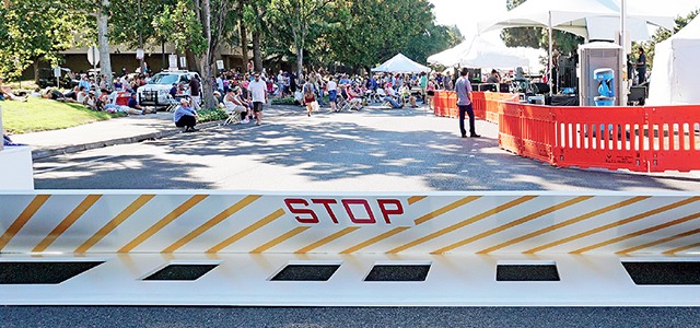
As pointed out above, the spring assembly 54 puts in a constant pressure on the web cam, while the electromechanical actuator may be controlled to exert a variable pressure on the cam, consequently allowing the training and decreasing( i. e., deploying and pulling back )of the wedge plate 16. In specific personifications, the constant force applied by the spring assembly 54 may be adjustable. g., electromechanical actuator) is disabled. As will certainly be appreciated, the spring assembly 54 may be covered and secured from debris or various other aspects by a cover plate(e. g., cover plate 68 shown in FIG. 4) that may be considerably flush with the elevated surface 38 of the structure 14. As discussed above, in the released setting, the wedge plate 16 serves to block accessibility or traveling past the barrier 10. For instance, the obstacle 10(e. g., the wedge plate 16 )might block pedestrians or cars from accessing a residential property or path. As discussed above, the barrier 10 is connected to the support 30 protected within the foundation 14,
front brackets 71. As an outcome, the affiliation settings up 72 might pivot and turn to make it possible for the collapse and extension of the linkage settings up 72 throughout retraction and deployment of the bather 10. The link assemblies 72 cause activity of the wedge plate 16 to be restricted. If a vehicle is taking a trip in the direction of the deployed wedge plate 16(e. For instance, in one circumstance, the security legs 86 might be extended throughoutmaintenance of find out the barrier 10. When the safety and security legs 86 are deployed, the safety legs 86 support the weight of the wedge plate 16 versus the surface area 12. Because of this, the training device 50 might be deactivated, serviced, gotten rid of, changed, etc. FIG. 5 is partial viewpoint view of a personification of the surface-mounted wedge-style obstacle 10, highlighting the webcam 80 and the camera surface areas 82 of the training system 50. Particularly, 2 camera surface areas 82, which are referred to as lower webcam surfaces 83, are placed listed below the webcam 80. The lower cam surface areas 83 may be repaired to the surface 12 (e. For example, the reduced cam surfaces 83 and the mounting plate 85 might create a single item that is protected to the support 30 by screws or other mechanical fasteners. Furthermore, 2 webcam surface areas 82, which are described as upper camera surfaces 87, are placed over the web cam 80 and paired to (e. In various other personifications, interfering layers or plates might be positioned between the surface 12 and the reduced webcam surface areas 83 and/or the wedge plate 16 and the top cam surface areas 87 As stated above, the webcam
80 translates along the webcam surface areas 82 when the wedge plate 16 is lifted from the withdrawed placement to the released setting. Furthermore, as mentioned over, the springtime assembly 54 (see FIG. 3 )may offer a force acting on the cam 80 in the direction 102 via springtime pole 58, which may decrease the force the electromechanical actuator 84 is required to use to the camera 80 in order to actuate and raise the wedge plate 16. 1 )to the released setting(see FIG. 4). As shown, the web cam 80 consists of track wheels 104(e. g., rollers), which get in touch with and translate along the camera surface areas 82 during operation.